Interfaces
INTERFACES, the second category on SETUP, wires the parts the IOmcu reads: the INA228 current monitor and an output encoder on one I2C (Inter-Integrated Circuit) bus, the phase tap, the PD mini supply, and how the programming port receives a Hitec D series servo. Its 23 settings stand in five sections under the headings I2C BUS, PHASE TAP, BALANCE SENSORS, SUPPLY and PROG PORT; a heading is a row of its own with no keys. The settings are kept and saved like every other setting on SETUP. The panel writes each set-up to the IOmcu 500ms after the last edit, and only what differs from what the IOmcu holds.
The current monitors
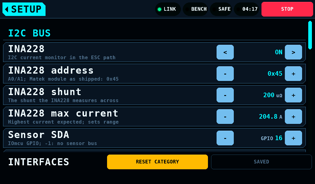
The IOmcu reads a TI INA228 in the ESC's power path, set up here, and up to four TI INA3221 on the same bus, set up on Sensors.
| Setting | Range | Default | What it does |
|---|---|---|---|
| INA228 | ON, OFF | OFF | the monitor in the ESC's power path |
| INA228 address | 0x40 to 0x4F | 0x45 | the MATEK I2C-INA-BM as shipped |
| INA228 shunt | 50 to 20000uΩ | 200 | the shunt it measures across |
| INA228 max current | 1.0 to 300.0A, 0.1A steps | 204.8 | the current the range is set for |
| Setting | Range | Default | What it does |
| --- | --- | --- | --- |
| Sensor SDA | -1, 0, 4, 6, 14, 16, 18, 20, 26 | 16 | the IOmcu GPIO (general-purpose input/output) for SDA; -1 sets no bus |
| Sensor SCL | SDA + 1, or -1 | 17 | follows Sensor SDA; the row has no keys |
- The bus runs at 400kHz; that is not a setting.
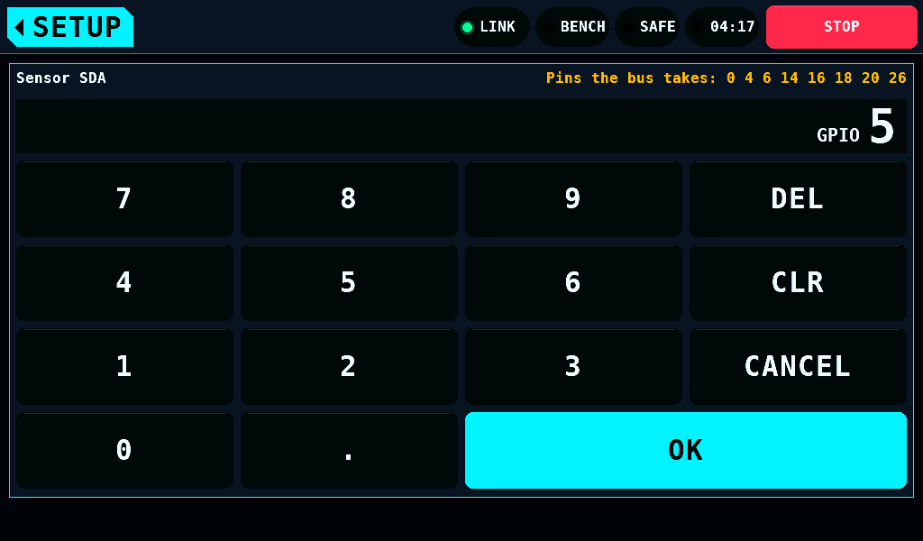
- The keypad refuses a Sensor SDA pin the bus cannot have and lists the pins it takes in place of the range: GPIO 5 typed shows
Pins the bus takes: 0 4 6 14 16 18 20 26. - The address stops at the ends of its range:
-at 0x40 and+at 0x4F change nothing. - Pins with nothing wired to them read as the monitors not answering, not as a blocked bus.
- The IOmcu takes a change only while the bench is SAFE.
- With the INA228 enabled and answering, the MOTOR & ESC tile loses its SIMULATED mark and MOTOR & ESC reads its voltage and current.
- With an INA3221 channel watching the servo tester's target on Sensors, SERVO reads the servo rail's current from it.
- A reading at the top of the range is shown as clipped, never as a value: 163.8mV across the INA3221's shunt.
- A monitor that stops answering does not switch the bench to SAFE: nothing trips on the monitors' readings.
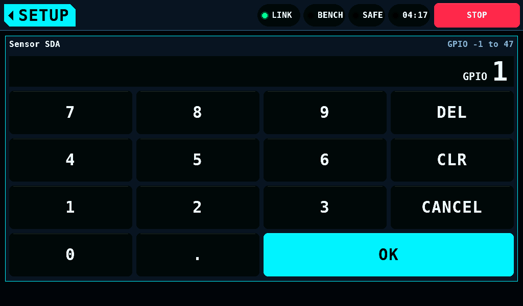
A pin is written with the word first, GPIO 1, in the keypad's entry, on the row and in the question on leaving SETUP unsaved. The keypad's header gives the range the same way, GPIO -1 to 47.
The band names what goes wrong, one message at a time, at most one every 5s. For example: Sensor SDA or SCL not set. Check SETUP > INTERFACES., INA228 and INA3221 both use 0x40. Check SETUP > INTERFACES., INA228 is not responding at 0x45., INA3221 0x40 CH1 clipped at 1.64A. Reading shows only the limit.. A message about the set-up -- pins not set, one address, a value rejected -- leaves the band as soon as the setting is right again and the IOmcu holds it.
A row the IOmcu does not hold
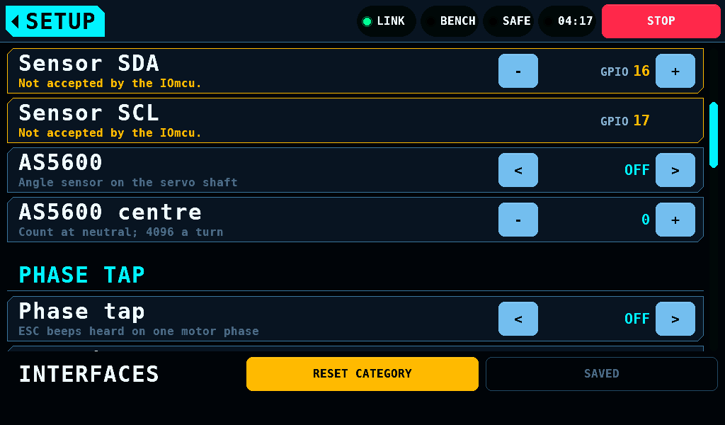
A row whose value is not the one the IOmcu holds has its edge and value in the warning colour, and its help line reads Not accepted by the IOmcu.. The mark shows:
- after an edit, until the write is taken: 500ms after the last edit, for the current monitors only once the bench is SAFE;
- on a value the IOmcu refused, until it is changed to one it takes;
- on a part switched ON that the IOmcu holds off: Sensor SDA at -1, the INA228 on the address of a fitted INA3221, or an IOmcu too old for the part.
No row is marked while no IOmcu answers. AS5600 centre is the panel's own value and is never marked.
The output encoder
| Setting | Range | Default | What it does |
|---|---|---|---|
| AS5600 | ON, OFF | OFF | an AS5600 magnetic angle sensor on the servo's output shaft, at its fixed address 0x36 on the sensor bus |
| AS5600 centre | 0 to 4095 | 0 | the count with the servo at neutral; 4096 counts a turn, 0.0879deg a count |
The encoder needs an IOmcu of 0.15.0 or later. ENC CENTRE on the servo settings sets the centre from the live reading. The band says when the sensor sees no magnet, AS5600 detects no magnet. Check the magnet on the servo horn shaft., or when the magnet is too weak or too strong. A magnet message is said once while the sensor's magnet status stays the same: an edit of another row does not repeat it. Switched off and on again, the sensor says it again.
The phase tap
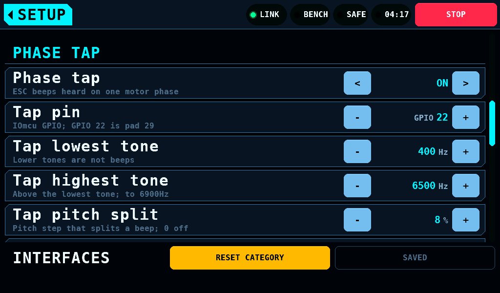
The phase tap hears an ESC's beeps on one motor phase. One IOmcu GPIO reads the phase through a series resistor and a zener clamp. The tap is an input: it drives nothing, and the IOmcu takes a change ARMED or not.
| Setting | Range | Default | What it does |
|---|---|---|---|
| Phase tap | ON, OFF | OFF | the capture runs on the IOmcu |
| Tap pin | 0, 1, 2, 4 to 7, 13 to 22 | 22 | the IOmcu GPIO; GPIO 22 is pad 29. The pins the RP2350-CAN brings out and does not reserve, less the ADC pins GPIO 26 to GPIO 29 |
| Tap lowest tone | 50 to 2000Hz, 10Hz steps | 400 | a lower tone is not a beep |
| Tap highest tone | 100 to 6900Hz, 50Hz steps | 6500 | above the lowest tone |
| Tap pitch split | 0 to 50% | 8 | a pitch change this large starts a new beep; 0 splits on silence only |
| Tap gap | 1 to 100ms | 3 | the silence that ends a beep |
| Tap min periods | 1 to 64 | 3 | the tone periods that make a beep |
The IOmcu refuses an ADC (analog-to-digital converter) pin, a pin bound to an output, and a pin the sensor bus or the PD mini holds. Tap gap has to be at least one period of Tap lowest tone: 3ms at the default 400Hz, whose period is 2.5ms. A rejected value's message leaves the band once the value is set back to one the IOmcu takes. The run page of ESC STICK shows the beeps.
Vibration and the optical tacho
| Setting | Range | Default |
|---|---|---|
| Vibration | ON, OFF | OFF |
| Optical tacho | ON, OFF | OFF |
| Tacho pin | -1 to 48 | -1 |
These three are stored. No screen or IOmcu reads them in this release.
The PD mini
| Setting | Range | Default | What it does |
|---|---|---|---|
| PD mini | ON, OFF | OFF | the programmable supply on SUPPLY and SERVO; OFF runs the panel's supply model |
| PD mini TX | -1 to 47 | -1 | the IOmcu GPIO to the module's DM |
| PD mini RX | -1 to 47 | -1 | the IOmcu GPIO from the module's DP |
| PD mini baud | 9600, 19200, 38400, 57600, 115200, 230400, 460800, AUTO | AUTO | the module's UART (universal asynchronous receiver-transmitter) rate; AUTO tries each of the 7 rates, one a second |
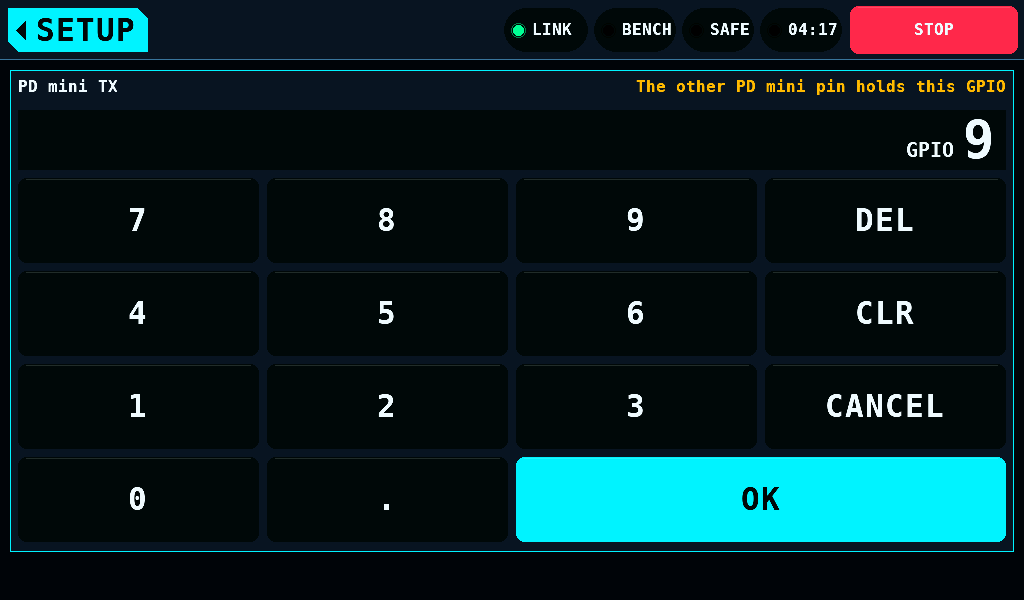
The - and + keys of PD mini TX and PD mini RX step over the GPIO the other row holds: with RX on GPIO 18, TX steps from GPIO 19 to GPIO 17. At either end of the range the key then does nothing: with RX on GPIO 47, TX stops at GPIO 46. The keypad refuses the other row's GPIO and shows The other PD mini pin holds this GPIO in place of the range. A set-up stored with both rows on one GPIO loads as stored; the PD mini stays off, the SUPPLY header says PD MINI NO PINS, and both rows say TX and RX on one pin. The PD mini stays off. until one of them is stepped. The PD mini switch turns the module off. The IOmcu refuses a pin that is reserved, bound to an output, held by the sensor bus or the phase tap, or the other pin: RX on GPIO 17 is refused while Sensor SCL is GPIO 17. The message leaves the band once the pin is set back to one the IOmcu takes. A change to the pins, the baud rate or the enable switch switches the supply output off.
The programming port
| Setting | Range | Default | What it does |
|---|---|---|---|
| Hitec D receive | PULL-UP, PRECHARGE | PULL-UP | how the IOmcu receives a Hitec D series servo's answer on the programming port. PULL-UP: a 2.2kΩ resistor from the signal wire to the servo supply. PRECHARGE: no resistor; the IOmcu drives the pad high for 100ns every 1.09us and samples it 113ns later |
The IOmcu takes the value at its next OPEN of a D series line. Classic servos (HS-5xxx, HS-7xxx) need neither and ignore it. An IOmcu of 0.21.1 or 0.21.2 (protocol 4.23) receives with PULL-UP; with PRECHARGE set the row then reads IOmcu older than 0.22.0: receives with PULL-UP. An IOmcu older than 0.21.1 has no Hitec line; with PRECHARGE set the row reads IOmcu older than 0.21.1: no Hitec line.