Outputs
OUTPUTS binds the IOmcu's pins to output protocols: which pins drive servos, which drive ESCs (electronic speed controllers), and with what signal. It opens from OUTPUTS on SETUP on the overview: OFF selected and every bound pin named by its protocol. From TARGET on MOTOR & ESC it opens on the protocol the throttle's pins are bound as (the overview while they are bound as several or none is known), and from TARGET on SERVO on what that row shows: the PROG PORT entry while the IOmcu drives the port, SERVO PWM while it drives the outputs, the overview while the target is not known. The home tag goes back to the screen it opened from; over the open protocol list it closes the list first, choosing nothing. The protocol list and LAST WRITE take the left column; the IOmcu's pins take the right. PICK A PIN holds the same binding on a drawing of the board.
Binding pins
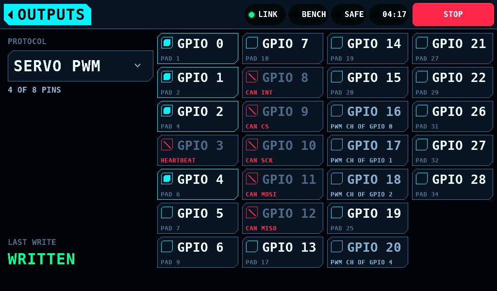
- Pick a protocol in the PROTOCOL list. Until then a tap on a pin does nothing.
- Tap a pin to tick it. A tick binds the pin to the protocol at once; there is no APPLY key.
- Tap a ticked pin to give it back.
- Pick OFF to go back to the overview.
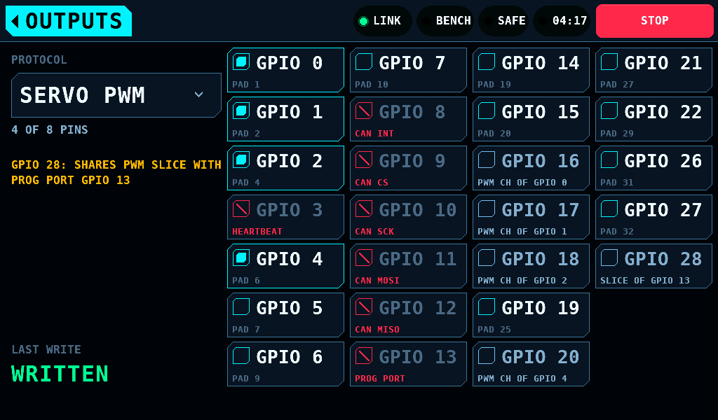
The count under the list, 4 OF 8 PINS, says how many pins the protocol holds and how many it takes. A pin belongs to one protocol at most. Several protocols can be bound at once.
Each ticked pin is one slot of the IOmcu's OUTPUTS page, in pin order across every protocol. The lowest ticked pin is channel 0. There are 8 slots and 8 channels, shared by all protocols.
The protocols
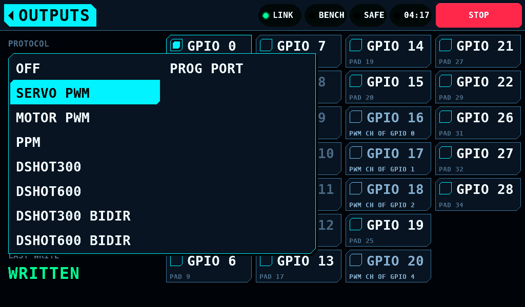
| Protocol | Signal | Pins |
|---|---|---|
| OFF | binds nothing; shows the whole binding | 0 |
| SERVO PWM | PWM (pulse-width modulation) at 50Hz, for a servo or a control surface | up to 8 |
| MOTOR PWM | the same pulse at 50Hz, for an ESC; from Idle pulse to Full pulse | up to 8 |
| PPM | PPM (pulse-position modulation): 8 channels on one pin at 40Hz | 1 |
| DSHOT300, DSHOT600 | DShot digital throttle at 300 or 600kbit/s | up to 8 |
| DSHOT300 BIDIR, DSHOT600 BIDIR | DShot with rpm telemetry from the ESC on the same wire | up to 8 |
A servo channel centres when nothing commands it; a motor channel stops. The pulse cannot say which is on the pin, so the protocol says it. The MOTOR & ESC throttle drives every channel bound as MOTOR PWM or a DShot entry, and leaves the servo channels alone. PPM needs 8 channels, so a bench with PPM bound has room for nothing else.
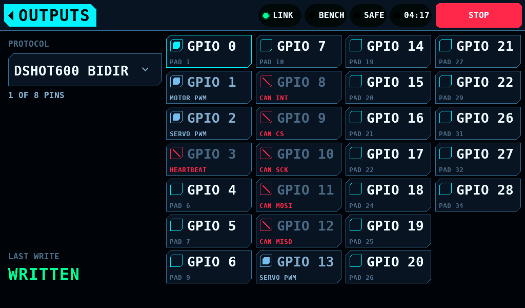
Picking a protocol writes nothing. It chooses which pins show as ticked and which protocol the next tick joins. The pins of the other protocols stay bound.
Idle pulse and Full pulse
A MOTOR PWM channel sends 0% throttle as Idle pulse and 100% as Full pulse, 1000us and 2000us by default. Both are on MOTOR & ESC, SETTINGS, in steps of 10us: Idle pulse 800 to 1600us, Full pulse 1400 to 2400us. A SERVO PWM channel keeps 1000 to 2000us, or the range SERVO sends. A change reaches the IOmcu 300ms after the last edit while the bench is SAFE. An Idle pulse that is not 100us or more below Full pulse is not sent, and the band says Idle pulse must be 100us or more below Full pulse. Not sent..
An ESC calibrated on a transmitter takes that transmitter's shortest pulse as zero. Set Idle pulse at or below that pulse and Full pulse at or above the longest one: for a transmitter that sends 985 to 2012us, 980us and 2020us.
What a pin cell shows
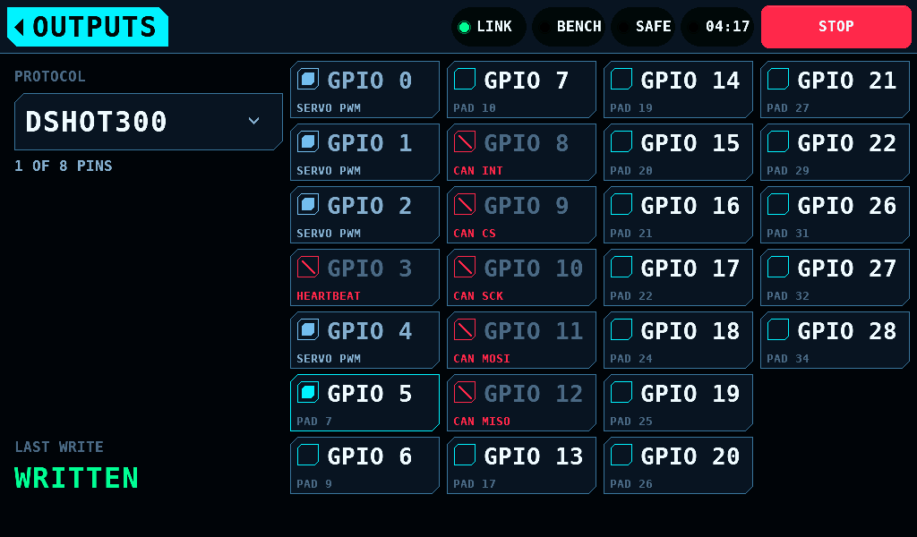
| Cell | Meaning | A tap |
|---|---|---|
ticked, PAD 6 | bound in the selected protocol; the pad number printed on the board | gives it back |
| greyed, the other protocol's name | held by another protocol | does nothing |
| red, struck through | reserved: GPIO 3 carries the safety heartbeat, GPIO 8 to GPIO 12 the CAN (Controller Area Network) controller | does nothing |
PROG PORT | the pin of the IOmcu's programming port, GPIO 13 by default | does nothing |
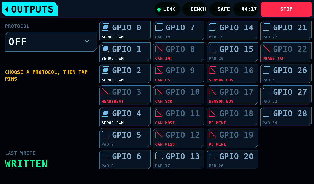
red, SENSOR BUS, PD MINI or PHASE TAP | a pin SETUP > INTERFACES holds: Sensor SDA and SCL while the INA228 or AS5600 is ON or an INA3221 is fitted on SETUP > SENSORS; PD mini TX and RX while the PD mini is ON with both pins set; the tap pin while the phase tap is ON. The cell follows those settings | does nothing |
greyed, SLICE OF GPIO 13 | under SERVO PWM and MOTOR PWM: the pin shares a PWM slice with a programming port's pin, any port the IOmcu reports; GPIO 28 and GPIO 13 are slice 6 | does nothing; GPIO 28: SHARES PWM SLICE WITH PROG PORT GPIO 13 under the count |
greyed, PWM CH OF GPIO 0 | under SERVO PWM and MOTOR PWM: the pin shares a PWM compare register with a pin bound as PWM (GPIO 0 and GPIO 16, GPIO 1 and GPIO 17, GPIO 2 and GPIO 18, GPIO 4 and GPIO 20, GPIO 5 and GPIO 21, GPIO 6 and GPIO 22) | does nothing; GPIO 16: SAME PWM CHANNEL AS GPIO 0 under the count |
free, PAD 7 | not bound | binds it |
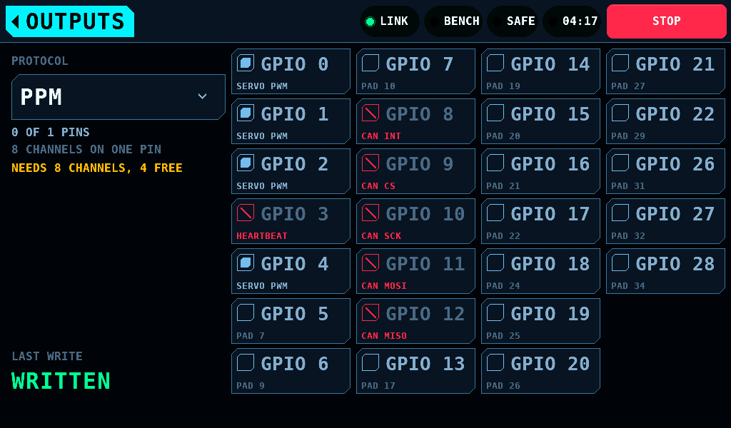
When the selected protocol can take no more pins, the reason stands under the count in amber: NEEDS 8 CHANNELS, 4 FREE, ALL 8 SLOTS IN USE or SERVO PWM TAKES 8 PINS.
A stored binding that holds GPIO 13 keeps it: the programming port then has no pin, and the servo programmer says so on CONNECT.
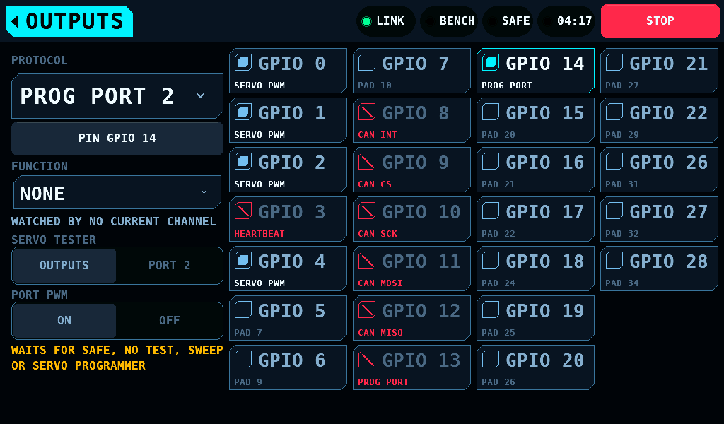
The PROG PORT entry
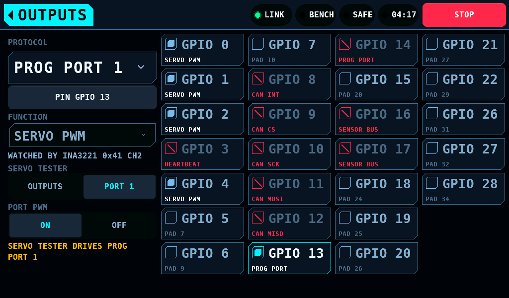
The open protocol list shows one PROG PORT entry per programming port the IOmcu reports, in a second column beside the protocols: 4 from IOmcu 0.22.0, 1 on an older build, and one for port 1 while the count is not known. An IOmcu older than 0.17.0 has no programming port and no entry. A programming port is an output of its own kind, no protocol and no slot. Every entry has the same rows:
| Row | Shows and does |
|---|---|
| PIN | PIN GPIO 13, SET A PIN, PIN GPIO 14 REFUSED or NO PIN KNOWN; a tap opens PICK A PIN on the port, where a tap on a pin sets it |
| FUNCTION | what the pin carries while no programming session holds it; a tap opens the list. SERVO PWM is the servo pulse on a PWM pin; NONE leaves the pin an input with its pull-down, on any free pin; DSHOT150, DSHOT300 and DSHOT600 (IOmcu 0.22.0 or later) send DShot from MOTOR & ESC's throttle, a frame every 1ms while ARMED for the throttle, on any free pin |
| WATCHED BY | the INA3221 channel that watches the port in SETUP > SENSORS, WATCHED BY INA3221 0x41 CH2; WATCHED BY NO CURRENT CHANNEL while none does |
| SERVO TESTER | OUTPUTS or PORT n: what the SERVO tester drives. SERVO's TARGET row opens OUTPUTS here while the IOmcu drives the port |
| PORT PWM | ON or OFF: the pulse of the port that is the tester's target |
The IOmcu keeps each port's pin and function in its flash, with the outputs' binding: they belong to the board. Port 1 starts as SERVO PWM on GPIO 13, ports 2 to 4 as NONE with no pin. A FUNCTION tap and a pin tapped in PICK A PIN are asks: the panel writes them on a bench at rest and the amber line says how they stand.
| Line under the rows | Condition |
|---|---|
LOCKED: THE SERVO PROGRAMMER HOLDS THE PORT | the servo programmer has a port |
WAITS FOR SAFE, NO TEST, SWEEP OR SERVO PROGRAMMER | an ask for this port waits for a bench at rest |
THE IOMCU REFUSED IT | the IOmcu refused the last ask, or did not answer it |
LINK LOST BEFORE THE WRITE | the link went down before the ask was written |
PORTS NOT READ YET | the IOmcu's ports not read since the link came up |
LOCKED WHILE ARMED OR A TEST OR SWEEP RUNS | the bench is ARMED, or a sweep or a test runs; PORT PWM still goes off |
SERVO TESTER DRIVES PROG PORT 3 | the tester drives another port |
THE SERVO TESTER NEEDS FUNCTION SERVO PWM | the port is NONE or DShot |
IOMCU OLDER THAN 0.22.0: SERVO PWM ONLY | the IOmcu has no FUNCTION |
PORT PWM NEEDS PROG PORT AS THE TESTER'S TARGET | PORT PWM on a port that is not the tester's target |
Picking the entry writes nothing to the IOmcu, and LAST WRITE is not shown on it. The tester's two settings are kept on the panel and reach the IOmcu on a bench at rest. With more than one port the entries read PROG PORT 1 to PROG PORT 4.
The overview: OFF
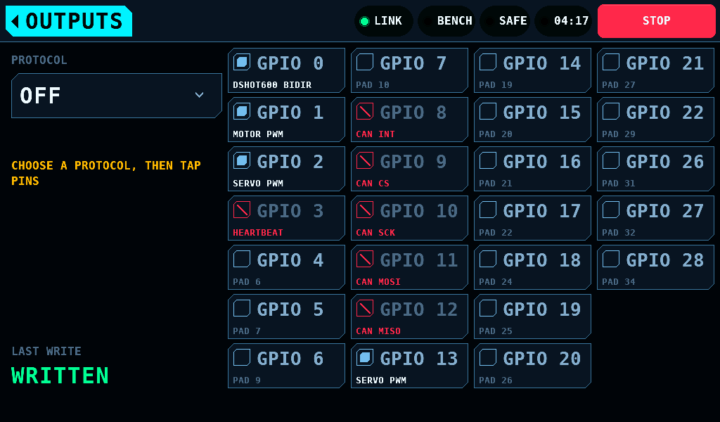
Every visit from SETUP opens with OFF selected. OFF binds nothing and unbinds nothing. Every bound pin shows the name of its protocol, so the whole binding and every pin it drives are on one screen. A tap on a pin does nothing, and the line under the list reads CHOOSE A PROTOCOL, THEN TAP PINS. Opening the screen writes nothing to the IOmcu. OFF stays selected until a protocol is picked, also across leaving the screen. A change of board, such as an IOmcu that answers during the visit or one swapped for another, selects OFF whatever was selected, so a protocol picked before is not carried to it. Pick a protocol to edit its pins; pick OFF to come back here. PICK A PIN opens with OFF selected too.
LAST WRITE
Every tick is written at once. The panel then reads the IOmcu's pages back and shows what it holds.
| LAST WRITE | Meaning |
|---|---|
NOT WRITTEN | nothing written since the panel started |
WRITTEN | the IOmcu acknowledged the write |
NO LINK | an exchange got no answer within 1000ms, or the link is down |
REFUSED | the IOmcu refused: a pin it cannot bind, a change while ARMED, or a frame rate it could not put back |
An IOmcu of 0.15.0 or later takes the binding whole: NO LINK and REFUSED leave the binding in force as it was.
A binding that is not confirmed
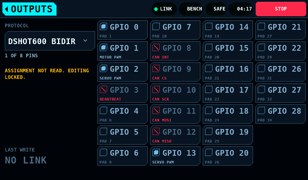
The screen edits a binding only after reading it. While a page did not read, the screen keeps the last binding read, dimmed, with ASSIGNMENT NOT READ. EDITING LOCKED.. A tap on a pin does nothing, here and on PICK A PIN. The panel reads again at every link-up and every 500ms.
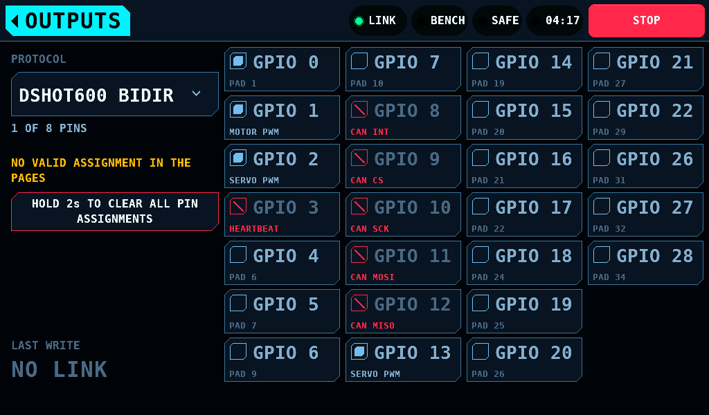
When the pages read but describe no binding the screen knows, for example one pin in two slots, it reads NO VALID ASSIGNMENT IN THE PAGES and offers HOLD 2s TO CLEAR ALL PIN ASSIGNMENTS. Held, it writes a binding with no pin, and edits are taken again. A finger that leaves the key, a lift before 2s or leaving the screen abandons the hold.
The IOmcu keeps the binding
The IOmcu stores the binding in its own flash and restores it at boot; the panel never stores one. A restored binding claims its pins and holds them at rest until the bench is switched to ARMED. A power cut during a save leaves the binding from before it.
Related pages
- Pin picker: the same binding on the board.
- Motor and ESC: the pins the throttle drives.
- Servo settings: the pins the servo tester drives.